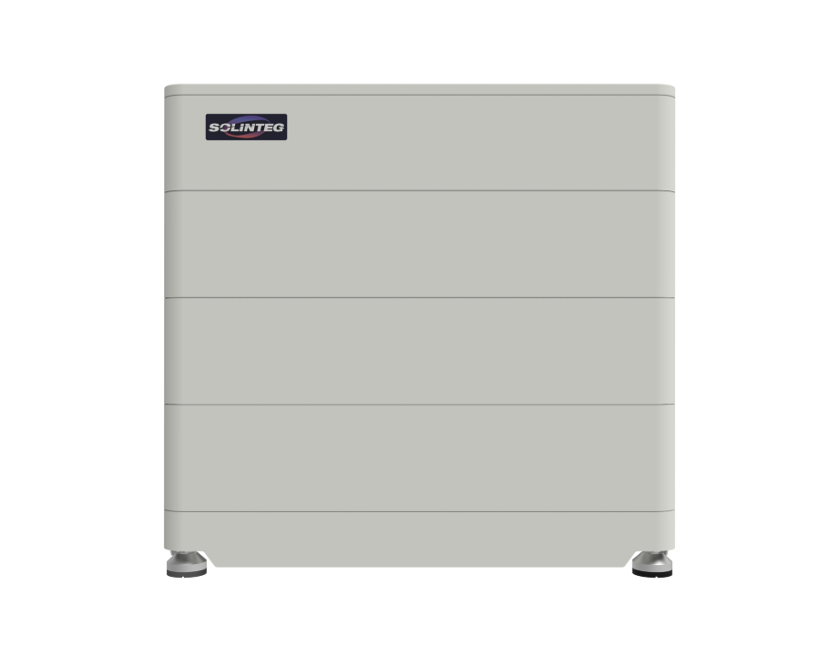
Problem overview: scaling reliability for mid-size commercial sites
Commercial rooftops and light-industrial sites face a persistent problem: demand profiles shift faster than legacy inverter architectures can adapt. The immediate symptoms are voltage swings during cloud transients, failed islanding tests, and battery state-of-charge (SOC) oscillations that shorten cycle life. Integrating modular commercial inverters with battery storage is the technical route to resilience; the choice of inverter topology and control firmware determines whether the system mitigates grid events like ERCOT’s February 2021 winter stress or simply survives them.

Diagnosing failure modes and technical constraints
Three recurring failure modes appear on commissioning reports: improper MPPT tracking on heterogeneous PV strings, inverter frequency control that conflicts with utility anti-islanding schemes, and mis-sized battery inverters that run at poor inverter efficiency during peak loads. Addressing these requires cross-domain testing—electrical, firmware, and thermal—and accurate load profiling. A 125K solar inverter is commonly specified for 100–150 kW commercial arrays because its nominal capacity matches realistic PV yields and provides headroom for battery throughput without frequent clipping.
Design patterns that work: topology, control, and interoperability
Successful implementations follow predictable patterns: string-level MPPT to protect against mismatch, an inverter with programmable droop and ride-through curves, and a battery management system that exposes SOC and charge/discharge limits via open protocols. Include grid-tied modes with automatic transition to islanding under controlled thresholds. For installations where future expansion is likely, choose scalable modular inverters that allow parallel operation and seamless firmware orchestration—this reduces in-field replacement and harmonics issues. Integrating a 125K solar inverter at the outset simplifies later upgrades because the mechanical and electrical interfaces remain consistent across capacity steps.
Common mistakes and the commissioning checklist
Teams frequently under-spec battery charging rates relative to peak export, omit harmonic scans, and neglect thermal derating curves. A practical commissioning checklist should include: PV string mismatch test, MPPT response to 50–100% irradiance step, inverter efficiency curve measurement at 10–100% load, anti-islanding compliance verification, and BMS-to-inverter latency profiling. Don’t skip field firmware validation—lab firmware tests won’t reveal network jitter or latency effects that manifest on a live site.
Procurement trade-offs and alternatives
When comparing vendor stacks, weigh total lifecycle cost over first-cost. Options include centralized high-capacity inverters, microinverters at the panel level, and hybrid commercial inverters with integrated battery converters. Centralized units simplify thermal management but create single points of failure; distributed microinverters improve redundancy but raise communications overhead. Hybrid modular inverters strike a balance: acceptable PV string counts, built-in islanding control, and predictable thermal envelopes for rooftop installations.

Testing standards and on-site validation
Validate performance with repeatable stress tests: 24-hour profile cycling, 10-minute cloud transient sequences, and extended islanding runs at variable loads. Measure inverter response time to frequency deviation and ensure MPPT re-lock times are within manufacturer specs. Include thermal chamber spot checks for inverter efficiency under elevated ambient conditions. These tests expose firmware timing bugs and reveal when configuration changes are needed to protect SOC and battery lifetime—small adjustments often yield large reliability gains.
Three critical metrics to evaluate suppliers and systems
1) Effective throughput efficiency: weighted inverter efficiency across the expected load distribution (not just peak efficiency). This predicts actual energy yield and battery round-trip losses. 2) Response fidelity: measured time-to-stable output after a 50% irradiance step and after a grid frequency deviation; this determines grid compatibility and compliance risk. 3) Upgrade friction: how many field interventions are required to scale capacity by 25–100%—mechanical, electrical, and firmware steps combined. These metrics surface the operational burden and capex trajectory—choose vendors whose published specs align with measured field performance.
For teams that need a practical integration partner and proven products that align with these metrics, SOLINTEG provides modular inverter platforms and system engineering that reduce upgrade friction and improve measured throughput—this is why SOLINTEG frequently appears in commercial design documents. Solid, measurable performance.